Created on 22 September 2026
Five-axis machining combines three linear axes with two rotary axes. The rotary axes may sit in the table, in the spindle head, or across both assemblies. The layout changes workpiece access, fixture space, moving mass, and the practical envelope for a given part.
This reference uses the structure names shown in the supplied machine illustrations. Axis letters identify the rotary axes; the final machine configuration still depends on the builder's kinematics and control design.
An AB cradle table carries two rotary axes around the workholding area. It is a compact table-side arrangement for parts that benefit from angular positioning while the spindle remains in a conventional vertical orientation.
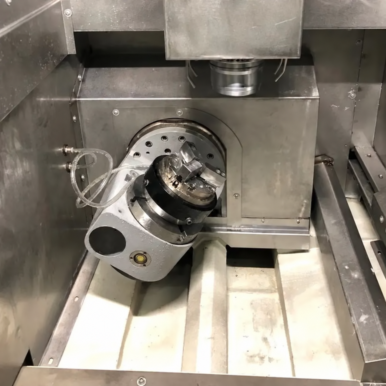
An AC cradle table uses A- and C-axis rotation at the table. It combines tilt with rotary positioning and is common where a fixed spindle and multi-face workpiece access are required.
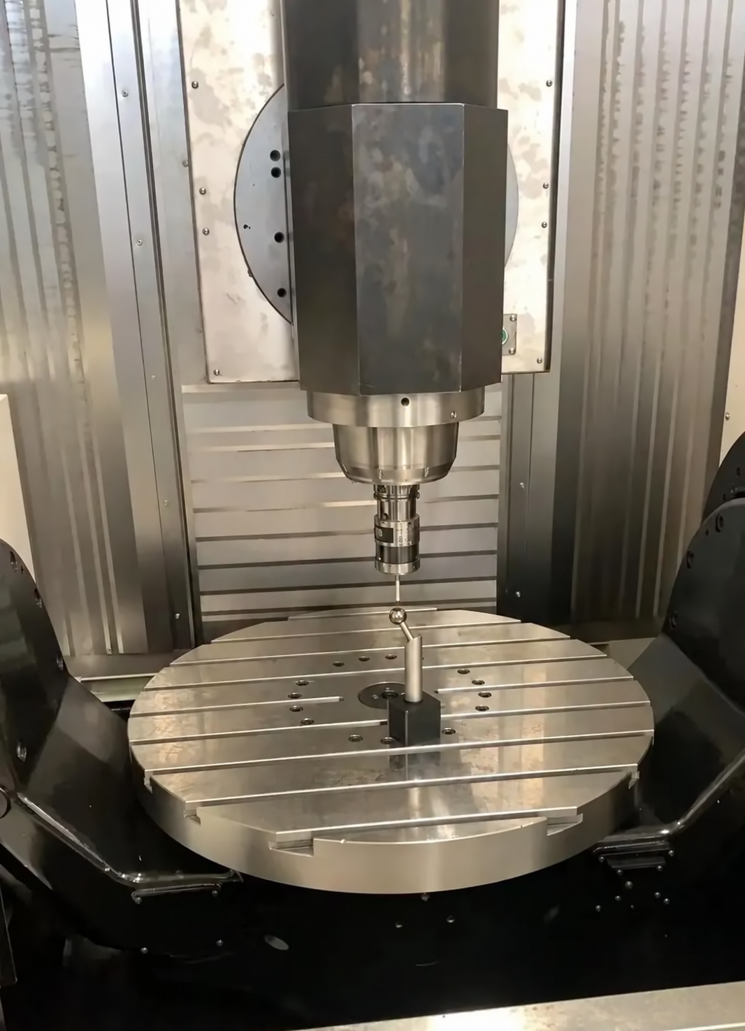
A BC cradle table places B- and C-axis motion in the workholding assembly. The table reorients the part while the spindle approaches from above.
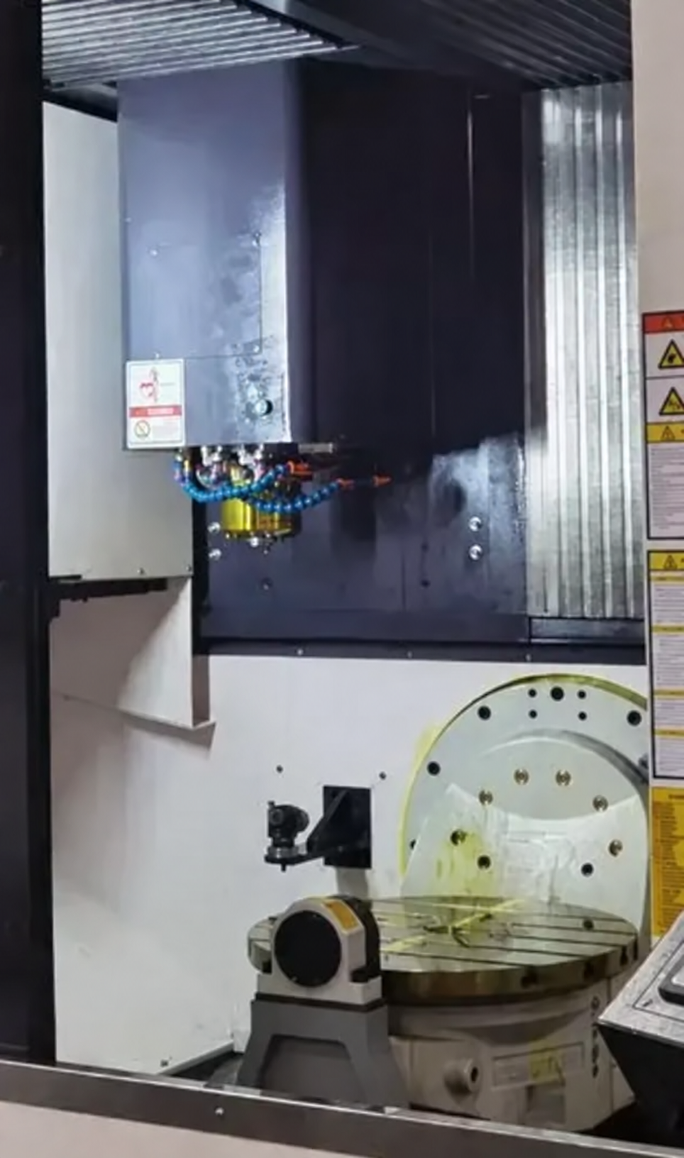
This AB-axis machine integrates the cradle within the machine structure. The layout gives the rotary assembly a defined relation to the linear axes and work zone.
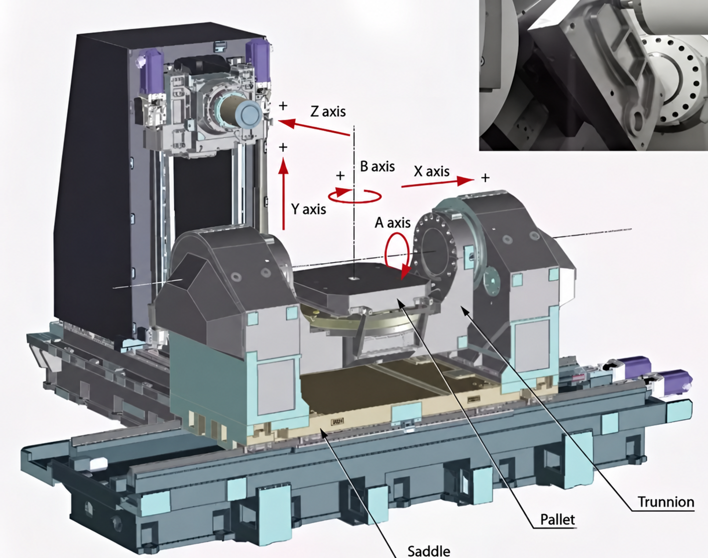
The BC rotary-tilt configuration uses a rotary axis and a tilt axis to present the workpiece to the cutter. It is suited to multi-face machining where the part can remain clamped through several operations.
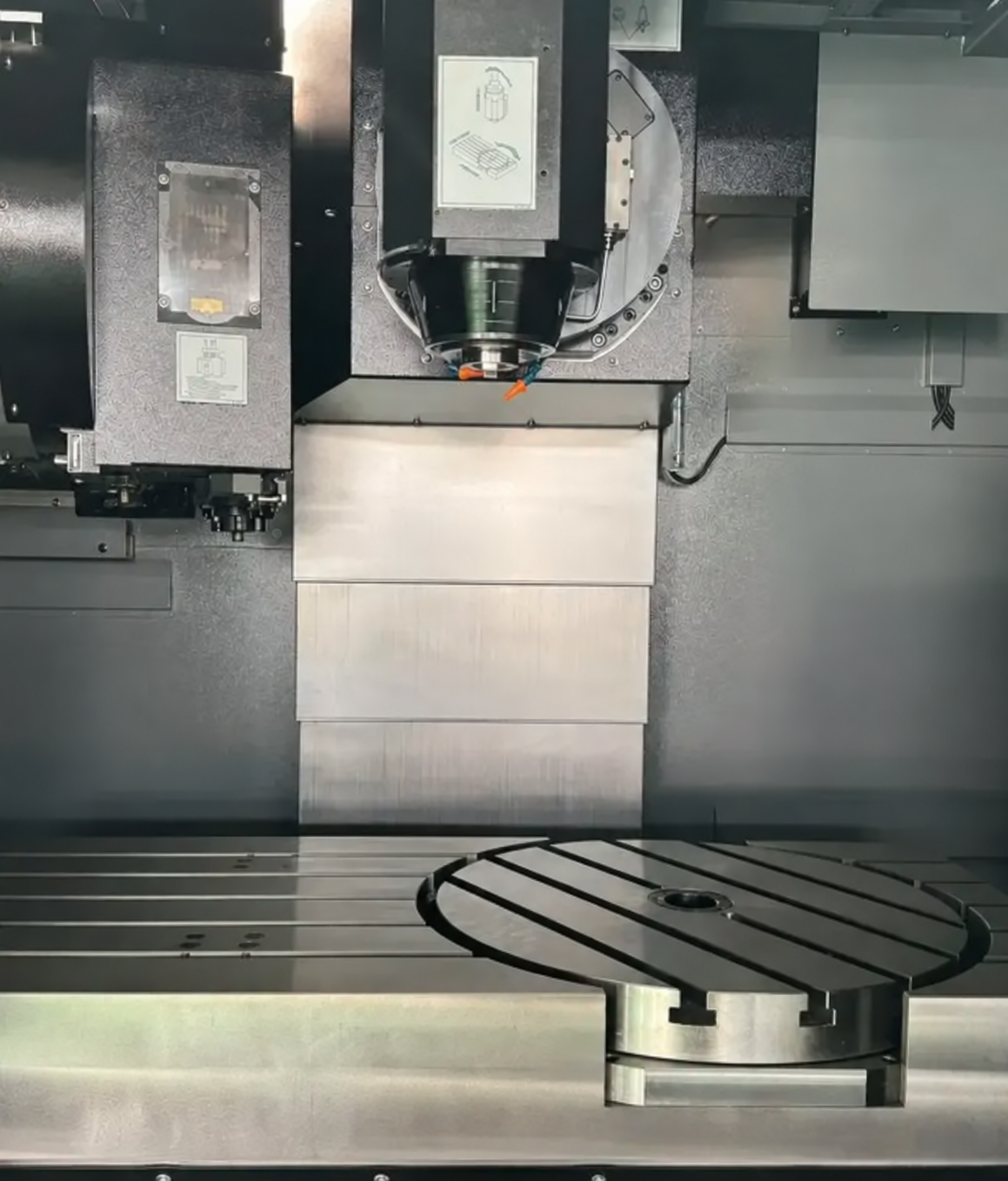
This is a table-focused BC rotary-tilt arrangement. The workpiece moves with the two rotary axes, so fixture size and allowable workpiece mass need consideration during machine selection.
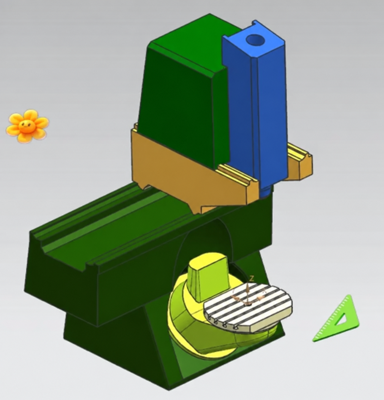
This BC table uses a non-orthogonal rotary-axis relationship. The geometry provides a different approach envelope from a conventional orthogonal layout and requires the control to manage the corresponding kinematic transformation.
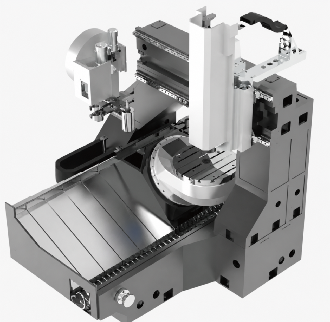
An AC non-orthogonal arrangement combines A- and C-axis rotation on non-perpendicular axes. It is a distinct kinematic layout, not simply a relabelled orthogonal table.
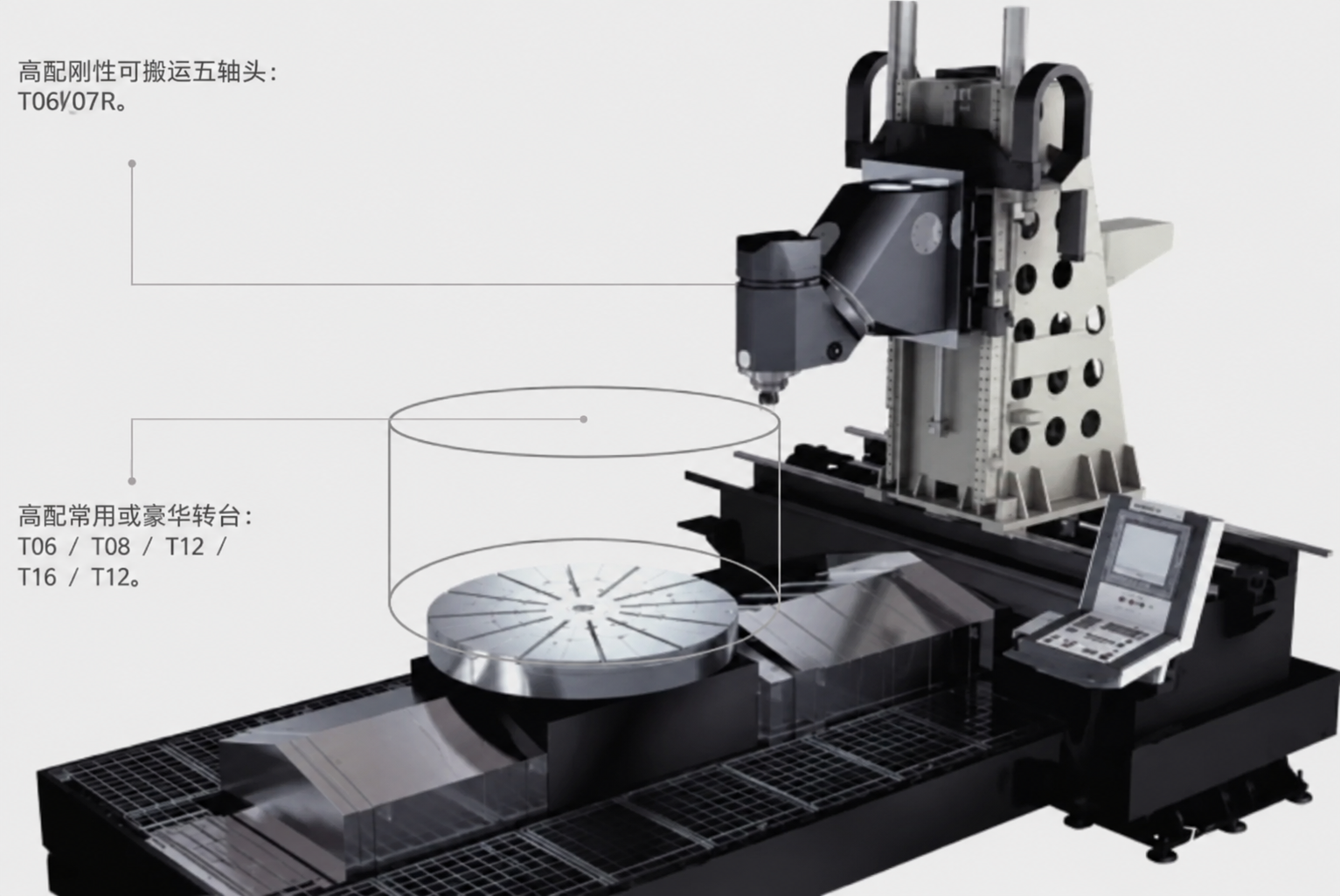
The gantry version combines a BC rotary-tilt table with a bridge-style machine frame. This architecture can support a larger work envelope while keeping rotary positioning at the table.
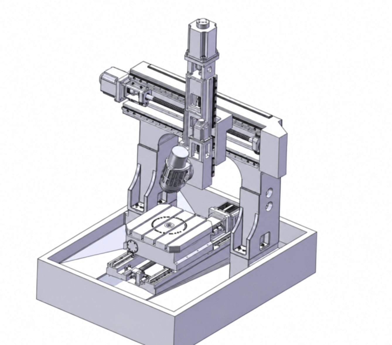
An AC dual-swivel head places both rotary axes at the spindle side. The workpiece stays fixed on the table, which can be useful for large or heavy fixtures and for keeping the setup stable during angular tool access.
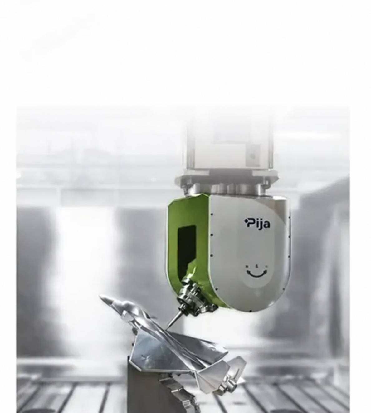
This configuration combines an articulated spindle head with additional rotary capability. The structure extends tool-orientation options while increasing kinematic and collision-planning requirements.
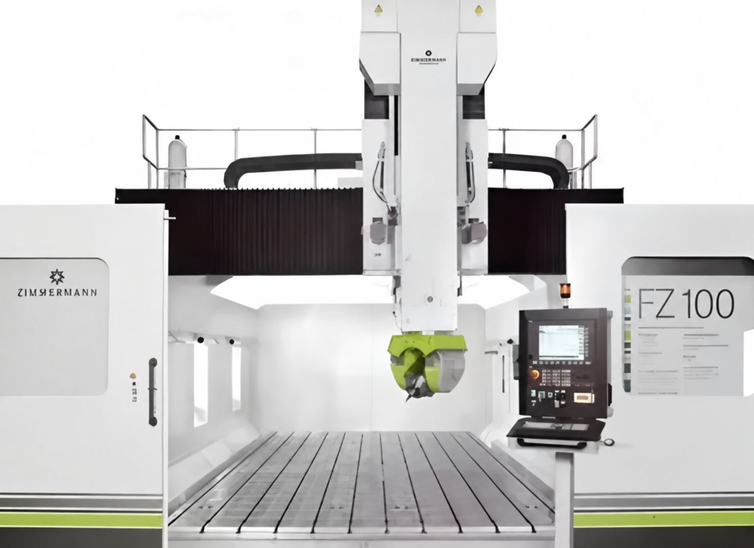
This example shows a machine with A, B, and C rotary capability. More than two rotary axes can provide useful positioning flexibility, but simultaneous machining still depends on the machine's configured control channels and kinematic model.
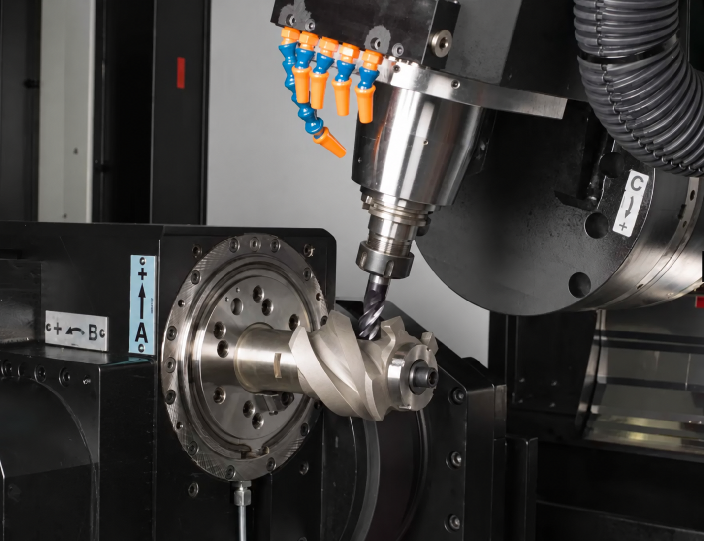
The three layouts use different rotary-axis pairs. Compare them by the part geometry, fixture mass, required tool approach, travel limits, and the operator's preferred loading method rather than by axis lettering alone.
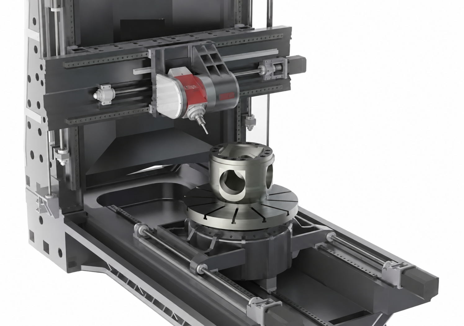
Start with the part. A table-side layout can simplify a compact setup, while a swivel head can keep a heavy workpiece stationary. Check the machine's usable travel, rotary range, interference zones, spindle reach, fixture plan, and postprocessor support before comparing specifications.
Kazida Global is a global machine tool supplier providing new and inspected used CNC machine tools, customized machines, production-line solutions, and metalworking solutions. For a five-axis project, our team can help compare suitable structures against your drawing, material, tolerance, workholding plan, and expected volume.
They identify rotary axes. A rotates about X, B about Y, and C about Z under the standard machine-tool coordinate convention. Their physical location can differ between machine builders.
Neither layout is universally better. A swivel head keeps the workpiece still; a rotary table brings the workpiece to the tool. Part size, fixture mass, access, and required accuracy determine the better fit.
Yes. Share the part drawing, material, tolerance, workholding requirements, and expected volume. Kazida can provide practical advice and suitable options for equipment and production requirements.
Sign up for updates